Translate

Showing posts with label Strong Attic Floors. Show all posts

Saturday, September 9, 2023

An Attic Ladder Installed Diagonal to Attic Floor Framing

 In a very tall attic, let all HVAC ducts be buried under R49 insulation. Here is an example of method to protect all and to provide safety, with a maximum of flooring, safely accessible. Build always for service life of at least sixty years. Such service life adds orders of magnitude to the value of construction. Cheap construction is unaffordable. (Search my Perpetuity Math.)  Build the floor 17” above drywall as dictated by economy in using 16” rips of plywood as webs in a complex box beam structure. Beam lower elements are the found floor joists whatever their dimension. Beam upper elements are typically upright 2x4s of maximum length. There is common practice to be applied in the density of screws or nails bonding webs to the 2x framing, Beam bottoms are room drywall. Beam tops are the plywood flooring, demanded for strength. Let attics be useful, with simple and sturdy storage lifts that add to user safety.


Such a thick floor was needed where a best attic ladder would be at 45° vs. framing.


Diagonal placement is really quite easy. Here it was wanted in part to allow painless repair of a ceiling fracture in a misstep while installing electronics wiring in the usual attic conditions of darkness and danger. The ceiling cut consumed the broken drywall. The diagonal placement is least obstructive in the hallway, and egress is off the path of work in the attic.


An attic ladder may be simple architectural beauty. This ceiling cut will be almost invisible with the ceiling repainted. The hole is well barricaded, with cautious approach in a step-off well.


The found access was the typical drywall plunker-hole in a bedroom ceiling. A R38 fiberglass batt was stapled to the fragile drywall with phony insulation value, really only R5.7. Do the "Insulation Math"     I am the never-questioned author of a definition of that phrase


A batt must be undersize, else too much drag, a problem especially in closure.

This frame is 22.8” x 31.4”. The R38 unfaced batt is nicely square-cut 22” x 23”.

The fraction of drywall area covered by the batt is 22*23/22.8*31.4 = 0.707.
1/(Reff + 3) = 0.293/3 + 0.707/41

Reff = 5.7

Reff + 3 is the total heat transfer resistance number, and the inverse, U = 1/(Reff + 3), is 

U = 0.10


Here is the ladder plan, where a very strong ladder rough box beam frame bears directly on the surrounding walls, and two floor joists, cut, are captured by the ladder frame.


Surrounding flooring ties to the ladder frame, with a walking surface 17" above ceiling drywall. This space is ample to move HVAC ducts to the attic floor, with safe, level, trip-free walking over a large decked area.


Under construction, see found inefficient HVAC ducts that had to be dodged to install the ladder, in August 2016. Construction was then paused to October, when HVAC would not be missed for awhile. For a complete story of this construction, consult the job photo album.


Here are photos of the finished, safe and useful attic.


The found attic access is converted to a storage lift
. Near the lift, the 17" floor level is maintained beneficial to coverage of HVAC ducts, but not needed for floor strength, Energy efficiency at the lift hatch is improved, a little bit. The U-value is reduced from 0.10, to 0.09. Just learn that a stapled-on R38 batt is mostly pretense of value. Actual value is achieved with thoughtful creation of functionality.


Wednesday, December 21, 2022

Doors: Some (or Much) Assembly Required

 Fifteen years into my service as business Attic Access, in metro Portland, Oregon, I find myself in a binge of calls for broken attic ladders made in Southeast USA, where fixing is the best response.

This now-repaired attic ladder, lightly used and perhaps thirty years old, was found dysfunctional at both limit arms, as I call them. The upper pivots were very loose, with springs and arms jammed akimbo; cleverness demanded to deploy or stow. It is now better-than-new and should live on another thirty years and more. With sturdy limit arms, longevity may come of care to not let step section hinges come apart with lost nuts and bolts.


Here is one of the flimsy mild-steel upper pivot cups from a much newer Werner WH3008 ladder that I demolished for recycling of the metal. The factory-installed limit arms were ruined when big rivets serving  as the upper pivots, ripped out. Functional replacement arms could not be found. The ladder would not have failed if the pivots had been strong lag screws binding to the ladder rough frame. The manufacturer sought simplest construction (the dumb rivets protruding here), installation-ready out of the shipping packaging. The installer overlooked the need to set long lag screws into the two holes not riveted to the ladder frame. The ladder frame then would measurably flex from heavy loads every time the ladder was operated, contributing to the pivot-rivet failure. 


Competent installers of ordinary doors have learned that lesser loads, even just the weight of a door, can not be supported by the door frame. Door loads are transmitted through the hinges, wanting to twist the frame. At every hinge, an appropriate screw to the flimsy 1x ladder frame, must be replaced with a screw binding to the much stronger, heavily nailed-in rough frame. 

The many-tricks in correct installation of an ordinary prefit door are well taught by trade show master presenter Gary Katz, The Katz Roadshow. I am a very uncommon resource, in offering useful techniques for the installation of an attic ladder, more tricky in its need to bear the very large loads of a person's weight and carried objects. Lesson One: Never rely on the ladder frame to bear the loads, despite claims of rated load-carrying. 

So, a ladder manufacturer will do well to include many installation steps that directly apply carried loads to the rough frame. Clearly describe them. Don't pretend that any uninstructed person with a saw, hammer and nails, can get the job done, with a rube helper, in a half hour. I fully disassemble a ladder for installation, safely and better, working alone. I sometimes extract the door from the frame. Arms and springs initially loose, are installed on the job. It takes a full day, and more, with needs of patching that often dictate the door removability.

With an attic ladder or any door, assembly is required.


In the ladder now to be repaired, study the failed upper pivots of the limit arms.

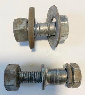
3/8" x 3 1/2" lag screws and large 3/8" washers replace a badly worn assortment of short machine bolts, a  bushing,  a couple of 3/8" nuts and a variety of washers loose and tilted at center of the cup mount.


Two 1/4" x 2 1/2" lag screws at each cup replace assorted wood and machine screws bound only to the 1x4 ladder frame, nuts falling the the floor when released.

All of this failed experimentation and years of frustration with the ladder would have been avoided if, from the beginning, at ladder installation, the springs, arms and cups had been packaged loosely, for assembly required of the installer, with lag screws as chosen now, binding to the rough frame. Choose drill sizes for the lag screws, that are not too large. Find the screw hole locations in the ladder frame clearly labeled.


At reset lower pivots of the limit arms, I made poor choices too, in reliance on fasteners from a nearby Home Depot. 3/8" x 1 1/2" coarse-thread hex bolts should have been 2" instead, permitting a washer  outside the arm and under a lock nut, at each side of the arm lower pivots. Home Depot is not a full-selection hardware store. They do not offer lock nuts for these coarse-thread bolts.  Find the lock nuts at an Ace Hardware.


I learn, and I share my learning.

A Typical Job, Completed January 2023

A Safety Pole and More: (Very much assembly is required of a competent and risk-averse installer.)

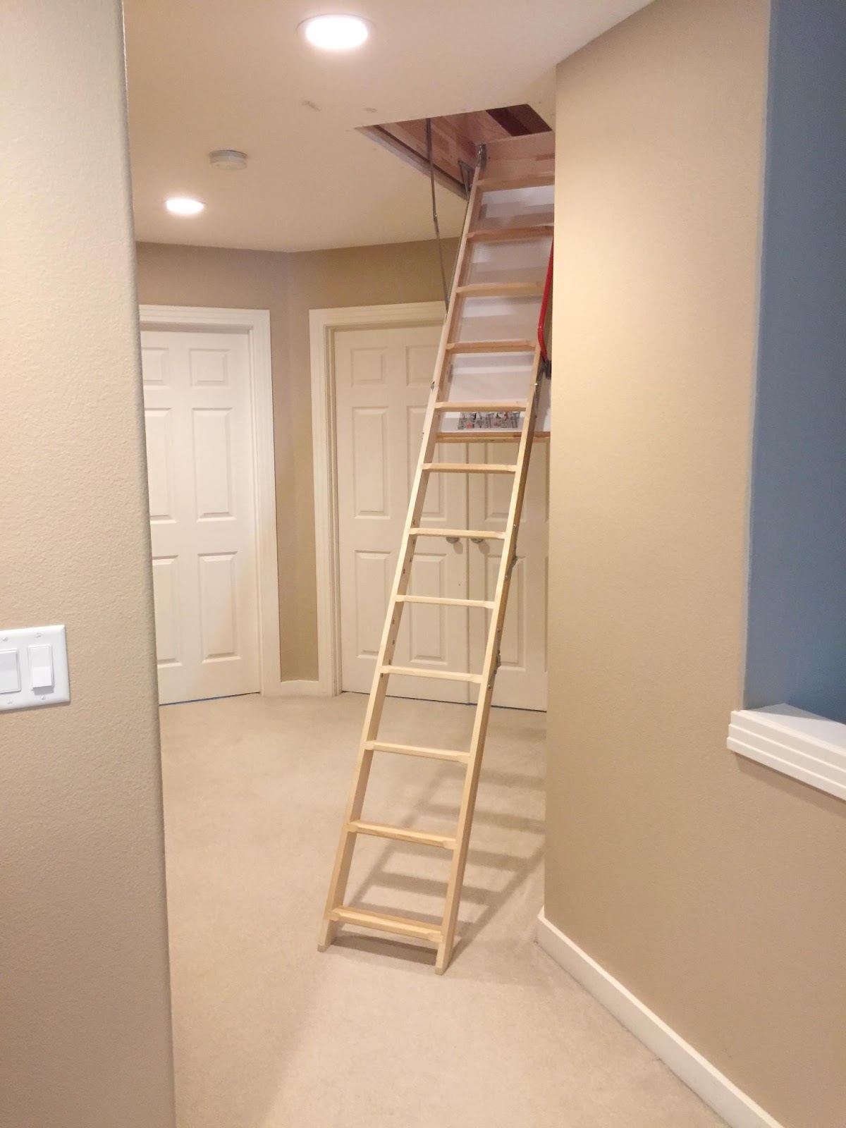
I install ladders with mandatory inclusion of every important safety measure I have imagined. A safety pole guides one from and to the ladder opening. When beyond reach of a ladder handle. always have your weight borne by a hand at a sequence of safety pole grips. A safety pole is a selected pretty 2x4 rock-solidly bridged between floor joists and roof joists with three or more hand grips, and with power and lighting control attached. Safety is priceless, and affordable. 

This is my job-in-process at late-December 2022, I keep divots of the plywood flooring cut about the ladder nearby, and set them to cover the hole while working distant from the ladder.


A lighted switch, readily visible and at-hand, greets the attic user.


The ladder is MidMade LEX 70 22/47, manufactured in Northern Sweden  sheltered workshops, by handicapped, talented workers, with superior, knotty, non-splitting Norway Spruce, from local forests.

The work of a competent installer can include much custom assembly specifically suited to the unique opportunities in any home.

 .


My safety measures are original as far as I know, not offered by any other installer, and yet are  extremely important. One measure is deployment at default 60° steps angle. This is improvement from the unsafe default, out-of-the-box 70° for this MidMade ladder. Added hinging in the center section is needed to achieve the safer angle. 

Here watch YouTube video of my deployment at 60°, with a very similar ladder.
Perfectly ordinary. Nothing to it, once imagined, for me.


These are the conditions upon destruction of the found drywall-plunker access at the January 2023 Midmade ladder.


Planning comes of much experience and fresh tactical thinking. The accurately-fit "hole" will be in a strong, completely rebuilt floor.


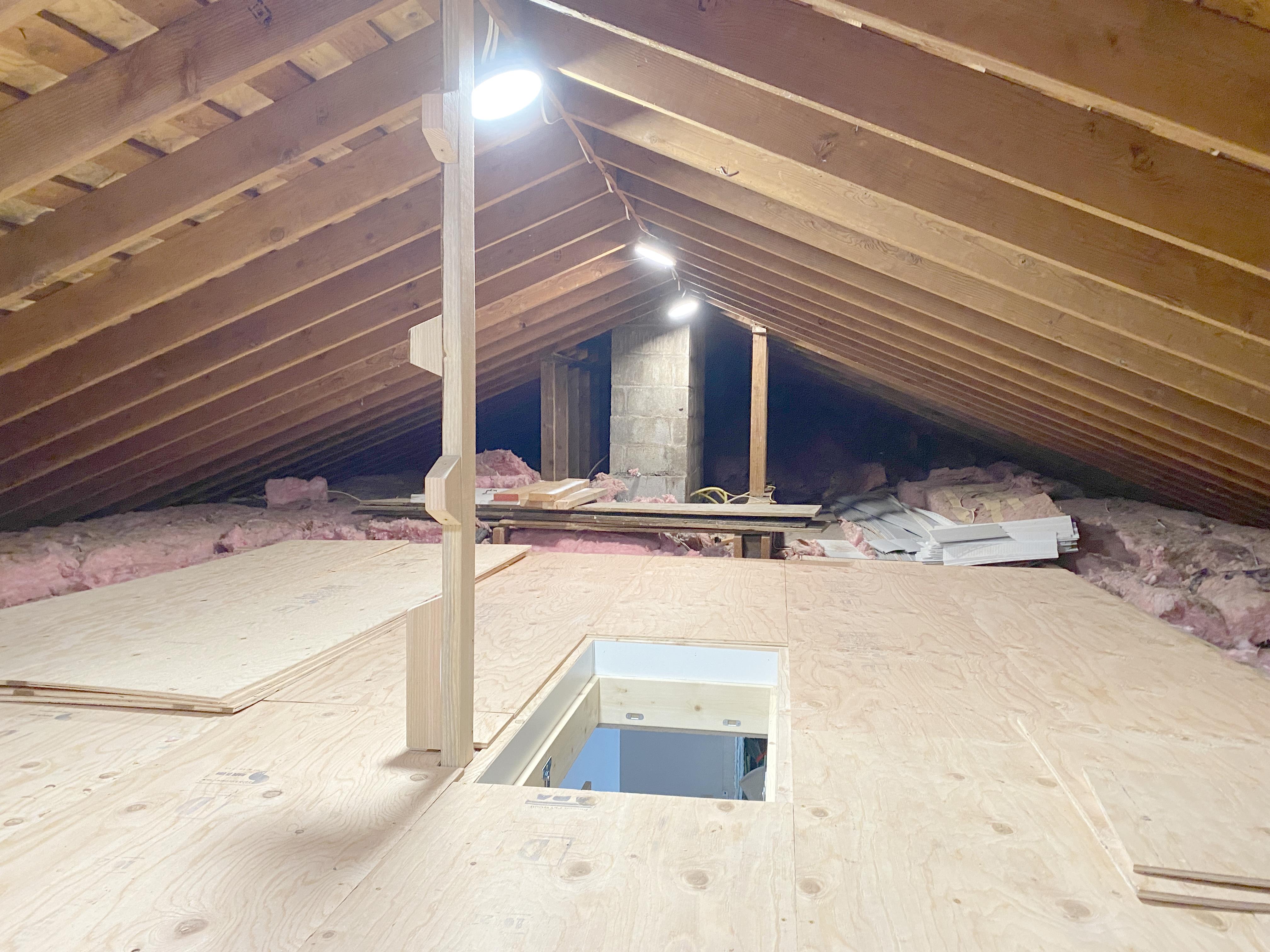
Here I am standing on the ladder, looking at the finished attic.


In the attic, looking back at the ladder, at left see three more matched sets of plywood 24" rips intended for further flooring progress. At right see the divots of the flooring cut for the ladder. Further progress is daunting. Upright 2x4s outboard of the chimney defy easiest passage. More lighting is needed.  Reserve long  strips of the home's vinyl siding are obstacles, that may now move onto flooring.


 This is the attic ladder as received from USA seller Conservation Technology, in Baltimore, MD. Packaging and instructions indicate that the ladder is ready to use, when nailed into the miraculously-produced ceiling hole.


Stuff the unboxed ladder in the attic, and place it in the hole, with the door face resting on propped supports. Anchor the ladder frame with a few nails and remove the supports. Open the door. 


Just lop off excess of the lower step section, and you're done!


Untrue!


Working with ladders never seen before, I indulged in several months of measuring, drawing, studying, thinking and trials. My detailed planning employs precise 2D graphics drawn in Adobe FrameMaker at v5.5.6, which I have owned and have daily employed for about twenty years. Circa 2002 the dotcom crash crushed a maker of CRT displays, in Beaverton, Oregon, and I acquired this miraculous tool for about $100. Bloated newer versions are useless to me. FrameMaker 2019, better only in faster 64-bit operation, might be purchased for $1100. Adobe wants, even demands, that I upgrade to a subscription at $39.99 per month, current version 17. In a thirty day free trial of v17 I couldn't accomplish anything. The graphics tools are not valued at Adobe, and are ruined.

Here is the site planning graphic in FrameMaker The imported Google Maps satellite photo has overlay of precise details of floor framing and all of my construction. All drawing is with the two simple palettes caught in the Snagit scan. The tools in FrameMaker 17 are horribly complicated by pulldowns and such for the likes of needlessly choosing between dozens of arrow shapes. 


Here again are the v5.5.6 tool palettes with drawing of improved ladder deployment, all hardware drawn at scale and noting the pinning of object groups. The ladder is much-improved beyond imaginings of a few naive inventors briefly employed a decade ago and not reimagined since, until I came along. With mid-splitting of the center section of a three-section ladder, adding hinges as a four-section ladder, limit arms and pivot positions are adjusted for deployment at a precise 60°. My reimagining of the ladder if the factory would cooperate for future production, would include elimination of what I consider a dangerous, trick, top step. I demand a broad top step for user safety. Here a probing foot  reaching out backward for descent, often first finds the pointy tops of the side rails. The danger is avoidable and the solution all-around has design and seller inventory-control advantages. There is no factory engineering staff to cooperate in this. So, just let me do the work? It is already done.


The as-shipped (default) ladder deploys at a too-steep 70°.steps and door angle, and I consider that unsafe. The steepness is needed for the deploying steps to clear the ladder frame. This ladder is assembled with too-small screws as if with intent an installer would rearrange things, then setting appropriate screws. European rule EN 14975 states that steps angle should not be steeper than 61°. Do not defy this rule! .Be grateful for means of compliance I offer, with added hinging.


Please see many issues of imperfect assembly of the default ladder. With this, then grant that improvements are just that. Intelligence added for the end-user must only reduce manufacturer liability, not affecting the manufacturer warranties.  The upper step section is cleverly bonded to the door via wood crossbars that reach out to the strong wood of the door edges, awkwardly. The lower crossbar is high up on the door, for no good reason. I will apply common sense to move that crossbar and its brackets, also replacing screws that are needlessly short. I will apply long and strong deck screws to engage the rough frame at limit arm upper pivots, at the upper attachment for balancing springs, and at all arbitrary captures of the ladder frame to the rough frame. I stand behind the ladder and its assembly, for as long as I am still walking, with proper insurance. My best insurance is that customers should never have an accident, and that they are gratefully aware of safety measures that I invent and that they must not refuse. Least-steep angle, handle(s), safety pole(s), ladder placement to step toward with momentum to maximum attic headroom, and more. Few people think installation of a door is simple DIY. Fewer should think an attic ladder is DIY.


Added hinging is required for angles less steep than 67°. For 96" floor to ceiling distance, the four-section deployment does not require "tenting."


Placing the ladder opening over a door frame below was a new challenge. Facing the need to close the hole in a two day binge of effort, I found it necessary to tilt the door frame out of the way, with temporary removal of the door. Armed with chiseling tools at my next visit, I would then reset the frame with trial and error, perhaps moving the frame. I did that cheerfully, resetting the door easily, with much-improved fastening and alignment, in further practice of best methods, taught by Gary Katz.

See the simple beauty in frameless trim, with nearly-invisible gaps between ceiling drywall, and the pretty-white durable finish of the ladder door.


Needed door trim then, often of ugly and cheap material, poorly fit, only conceals energy-leaking large gaps.


I do much better, with the ladder nearly invisible. It is a big deal. Important invention!


All the planning and hard work result in an attic that is  accessible.

 Good things happen up here. 

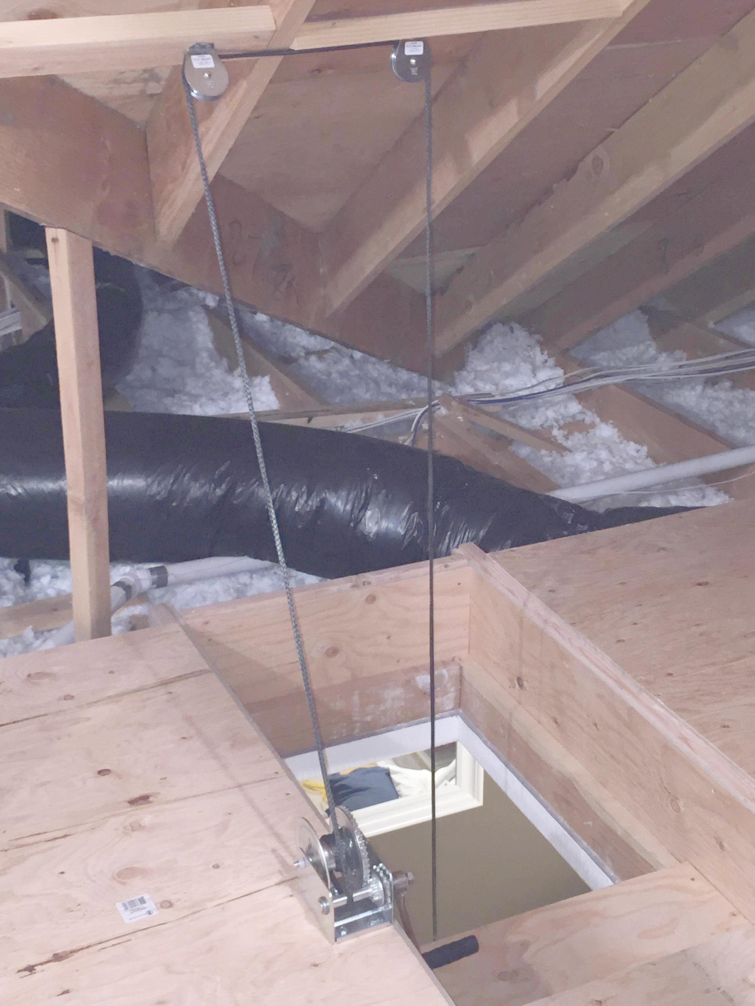
It's not about storage space for most of us. Here an electrician, with my work nearly done, safely fixed a list of photographed, not yet covered DIY wiring crimes. 

HVAC linesets are safely buried, intimately shrouded by batt insulation, under the flooring.

At and beyond a house-central large chimney, much is left dark and dangerous. 

Passageways for many mouse families are still a problem.

Elapsed time for the work; thirteen days.

102 hours of on-job labor.
$1625 materials, my cost.
Invoiced $3625, me then netting $20 per on-job hour, with yet no compensation for 876 miles and twelve hours of travel to this exotic location. 

My weatherization work and business practices are an ever-thoughtful experiment and have worked well enough that I have stayed at this for eighteen years. Soon age 79, I must wish to beneficially franchise the work globally, armed with useful owned URLs: AtticAccess.com, MidMade.com and more. I wish to team up with the competent USA importer of MidMade products, Conservation Technology, in Baltimore, MD, to avail architects and demanding home owners, of smart residence attic access and valuable improvement. We should agree that an attic is not a trash heap. It is an opportunity zone for easy gains of energy conservation and of providing security and data wiring, better ventilation, air conditioning and lighting of living spaces.

A $10,000 Attic Investment Makes Sense, Whether for Storage or Not

Many things we should preserve are tolerant of temperature swings. Yet, commercial storage of such is not less costly than conditioned storage. 

$150 per month, I think.
Cumulative Payments
Kept 1 year: $1800
Kept 5 years:$9000
Kept 10 years: $18,000

A $4000 investment in attic access here, or even $10,000 for the full attic, with a lift mechanism, is so much smarter.

For most of us, in single family homes, floored R38 or R49  attic access is a good investment just for maximum weatherization, with friendly opportunity to maintain wiring, lights, fans, plumbing and HVAC. Insulation prone to ruin by access is a very bad investment.

Home Advisor says of fragile blown loose-fill: "You’ll spend between $0.25 and $2 for every inch of thickness per square foot (one board foot) or $1 to $5 per square foot total." Four inches of loose-fill coverage of half of this example attic (1000 sq ft) would cost $1000 to $8,000.

My very superior work invoiced at $20 per hour is far too much, a bargain. My work creates accessibility. The almost-universal loose-fill alternative is a cruel barrier to accessibility and usefulness.

Monday, October 2, 2017

2x4 Framing Build-Out To 2x6


This is the most-read blog post  of individual Phillip Norman, of Portland, Oregon, USA.
(a grand-daughter draws a best smile)

Surely this post is of value to more than the few who have offered comments. I hope that an introduction will improve participation. I will share your credited story related to this, or to any of my posts. I welcome and will share criticism, where I might mislead.


Please consider virtue in the accurate and strong build-out of 2x4 to 2x6 thickness in this exterior wall section of my 1955 home in Portland, Oregon. Here is that build-out immediately upon demolition of the wall formerly separating the kitchen from an on-foundation concrete back porch. Found 2x4 framing in this exterior wall is strongly thickened to 2x6 with added 2x2s upon plywood box-beam webs. The extended kitchen has 2x6 outside wall framing.

This photo shows an initial setup with on-flat 2x6 segments at the floor. 


See that I could do much better, with a continuous upright 2x4 at the floor, shimmed out 1/2".  Want ability to nail floor moulding anywhere. Want least obstruction through the 2x6 sill plate, for angle-drilled plumbing. 


Here is my kitchen in a nearly-complete condition, September, 2018. Added depth of exterior walls was important too, to better framing of windows and a door, and simplified  plumbing and wiring.


Google the title of this post: 2x4 Framing Build-Out to 2x6 .
Find no one else offering what I do, employing only available dimensional lumber as-produced, and plywood rips. 2x2 is usable for plane perfection regardless of curl.

Summary graphics that follow, and the math of insulation values and heating costs are presented in this document:
Please find virtue in my simple Insulation Math. Find important conclusions in the applied math of the above-linked document, including:
  • I have achieved average R22 for a net of all kitchen exterior wall area, the same for new 2x6 walls and the 2x4 built out to 2x6. This is R-value as the inverse of carefully computed U-values. R value of employed insulation is nearly the same.


Here is the fix:


With clarity in what I do, I may digress to the bigger picture.

Detailed records of my construction process are in job photo albums:

I had despised drop-ceiling headers over kitchen cabinets. Such headers are awful heat bleeds in most homes, where at exterior walls they are not accessible for insulation. Too often, none of the headers are filled with insulation. I have the opportunity to expand my kitchen 40% with modest effort where the little kitchen exited to the back yard via a concrete porch fully on-foundation. 


It was a crummy little kitchen, and held down the usefulness of the house, beyond being the last room in my house where I had not demolished interior drywall to accomplish data and power wiring improvements, plumbing replacements and tight R15 insulation.

In this one room I would accomplish R22 wall insulation in 2x6 framing.


See my build-out to 2x6 thickness of an existing 2x4 wall. At top place an on-flat 2x4 and 1/2” plywood rip. Stitch on lengths of 5” rips of 1/2” plywood as composite beam webs. Place 2x2s true vertical and flat, leaving 1/2” thermal breaks of both the 2x framing and the webs. The 1/2” gaps behind 2x2s enable simple running of wires, without steel plates to mess up drywall flatness.

My kitchen overhaul occurred in stages, working by myself while improving my home in other areas and while working alone as a general contractor, never advertising:
Condition my crawl space, 9/2012 to 11/2012
Attic refinement, 1/2014 to 12/2018
Expansion onto porch, 8/2014 to 4/2015
Planning, 4/2015 to 7/2017
Completion, 7/2017 to 10/2018

Serious about this in late Summer 2017, I have reset the wall build-out to employ an upright 2x4 at the floor, for better baseboard attachment opportunity, and insulation a bit better.


I will have a much better kitchen, in a home that inspires possibilities with solidly-built homes of the 1950s. Details here are near-final. I do all work except cabinetry fabrication.

My circuit breaker panel is just beyond the garage wall that rounds this corner to the right. Most of the new kitchen wiring passes through the thickened South wall, with no need of nail-stop plates. See plumbing drains and vents well-reimagined in the crawl space below. All plumbing resides over the crawl space; none over the inaccessible former back-porch slab. Walls of the new half-bath will be elements of kitchen cabinetry, bolted to uninterrupted tile floor.

All appliance wiring passes along the South wall, including that to the electric range at the East wall. 


See four water service shut-offs under the kitchen sink. Spare Hot and Cold service without water to the refrigerator and disabling the dishwasher enable valved temporary plumbing to a temporary handicap shower unit possibly to be needed someday.


See invention of a module of wiring and plumbing devices that will plug into a careful rectangular cut through the back of the cabinet base for the kitchen sink. At right see some of the safe wiring opportunity, behind 2x2s of an outside wall bump-out to 2x6. Want that hidden wiring is fully revealed by removing outer/ top insulation batts.


Angle-drilling of kitchen sink water and drain lines is aided by the thickened 2x6 wall above.


The high end of house drain and vent piping, for a time, was at the laundry in the garage and at  the added half-bath.


See a more-elevated high point of the drain plumbing where a 1 1/2" ABS drain P-trap was added to collect consensate of the high-efficiency gas furnace and of a heat pump water heater. The kitchen overhaul with attendant new plumbing, enabled other important home improvements.


While exposed, the built-out framing was a laboratory of insulation methods, sharing photos in conversation with Insulation Institute .  I started out with an exceptional exterior wall judged to be R_total = 5, U = 0.2 not counting added value of wall joists and to-be-added insulation batts. To a generally-applicable R3 value of airtight sheating inside and outside, add  R2 value of Celotex sheathing . Exterior air tightness is achieved both at well-set old-growth cedar siding, and at overlap of Celotex edgesStart with less than half the conductivity and heating cost of common, cheap, non air-tight construction, Rtotal = 2.5, U = 0.4.


Walls built this way are to be treasured and preserved. I'm not sure what should be done with more-ancient walls, hopelessly leaky, hollow, cobweb strewn, with structural defects and dangerous wiring, ruined of insulation value. I suspect though that salvageable homes are determinant not by age, but by investment at time of construction.

Where is the pride of any employee or contractor of the US Department Of Energy paid to support residential energy efficiency, when USDOE Home Energy Scores treat all exterior walls without some insulation stuffing, as of paper, R_total = 0.4, U = 2.5 ? This perhaps-deliberately fuels older-home demolition regardless of solid construction. This is applied for all insulation opportunities, exterior walls, ceilings and floors. It encourages false claim that very-huge energy savings can be achieved by a blow-and-go scammer foolishly just adding some partial insulation atop wiring, plumbing and structural messes,
 if the home is not demolished.

The subjects with Insulation Institute  have been layering of batts to kill framing thermal shorts, full batt containment to avoid air circulation, and lack of value where insulation does not fully fill available space.


I wait, and wait, for recall of misinformation in this NAIMA instructional video of year-2012 . I bought and here tested a bag of the yellow Certainteed R13 insulation placed by the championed installer. Please watch the video, and see that the installer takes great care to not press edges beyond joist faces. I just don't know how to do that, making a fluffy batt 3" thick look like it fills the cavity space, as it must. It seems that alone among insulation manufacturers, Rockwool (formerly Roxul) , makes batts specified for a framing depth, that reliably fill the space. Look closely at the beginning of the video to glimpse Rockwool as exemplary insulation.


Here in my 2x4 garage wall, is a length of Certainteed unfaced insulation wrongly rated as R13 in a 2x4 wall. It has been placed here for more than a year, in incomplete communication with NAIMA, North American Insulation Manufacturers Association. At 2016 hearings for revisions to 2015 International Energy Conservation Code, NAIMA defended code-allowed underfill of framing, defeating my proposed requirement of full filling always, by overfill that accommodates small-batt tolerances


In fact, R13 batts NEVER fill 2x4 framing. Where gaps will exist all around a batt, then with low flow resistance for air. Air circulation, driven by energy convection and outside wind pressures, may reduce insulation value to zero. There is no reason this should be allowed.


At last rounding this corner with drywall, I apply last-minute grouting of a vent annulus, w
ith my always-available flexible grout. See that Rockwool R15 insulation  thoroughly fills the space, accurately cutting to width from 23"x 93" batts. Do the math on cost of this Rockwool vs. the experimental Certainteed R13 with no value, for one 16" oc frame bay, batt area 14.5*92/144 = 9.3 sq ft. The Rockwool cost $649 per 1000 sf. The R13 cost $397 per 1000 sf. The one batt cost, 9.3 sq ft, is $6, vs. $3.70. Proper code must keep a silly person from pocketing the negligible difference in installed cost. A DIY home owner must never be tempted to do wrong in a cheaper choice, by believing a "For 2x4 Framing" label on a crummy R13 bag.


Rounding the corner from built-out 2x6, to an ordinary 2x4 garage wall, report upon a layering trial to the right of that plumbing vent bay now filled with shaped R15. Where I have added a bath fan and overhead light junction box, 14/2 romex leads between a new 2G switch box and the attic, sandwich the wires between Rockwool AFB batts. See that R15 Rockwool is uniformly a bit thicker than 3 1/2". Two layers of AFB batts are 4" thick except as pressed in at edges, but better too thick for the space, than too thin.


I think insulation installers wrongly do not expect to find a family of batts that in layers, add up to fill the space, giving promised R-value.  AFB batts about R8 are not sold as suited for layering with object sandwiching.  2x6 walls may be filled with R23 Rockwool batts, or when necessary, with layered AFB:  R8 and R15.  2x4 walls may be filled just-barely, with R15 Rockwool batts, or when necessary, and perhaps better always, with two layers of AFB. Layering of manufactured consistent batts to deal with odd cavities, is not just good practice. Rockwool batts do not part, and hacked cuts make a big mess of a job, with puzzle pieces that challenge patience and result in deficient R-value. 


In new 2x6 walls, begin with AFB batts. there is certain ability to stuff an inch of effective insulation behind a crossbar that allows outlet placement distant from a 2x6 joist.


Here again see my trusty commercial bread-cutting knife, used for all cutting of batts. Cutting in and around friable Rockwool batts is easier and more precise than in stranded fiberglass batts. Where we admire honest, uniform thickness and easy shaping of Rockwool batts, also celebrate discarding of ill-conceived kraft facing as a leaky, crummy "vapor barrier." 


We need combinations of mineral wool batts that may sandwich wiring, as parting is just too awful.  One R15 batt and one AFB batt, or one R23 batt. nicely fill a 2x6 space. Doubled AFB batts as sandwiching in a 2x4 wall have excessive overfill. One needs many screws to pull in the drywall with compression.

Overfill is not the goal. Overfill is demanded only where batts have unreliable thickness, to get complete fill always.


With full demolition of drywall at the garage 2x4 wall, see dripped flexible grout from wall header sealing in the attic long ago. Plaster the gap now.


Seal the wall header fully.

For good reason and as demonstration of good example, buy a new coil of Resource Conservation Technology BG32 EPDM gasket.


The BG32 gasket consumed here will cost me less than $6. With flexible grout sealing of existing drywall, it will block a leakage path to the attic that is poorly accessible, and was not sealed before.


At the somewhat conditioned garage wall, insulate with R15 and layered-R8 Rockwool.


Finish GP Densarmor drywall pieced-in, using flexible grout and Structolite plaster, over joints well stitched with screws and backing lumber. Set joint paper tape in 24" lengths, at ceiling and wall corners only.


Date: 2/23/2018. Ideal condition for wall observation with an infrared camera. And, I don't own one. A camera investment of about $10,000 can have no economic return to me. I leave no voids, always maximizing insulation value. I believe there was nothing more to do, to  improve comfort and reduce operating costs at these exterior walls. I have at least the R23 before-framing-allowance achievable in 2x6 framing, with tight mineral wool batts. The modified 2x4 wall is yet-better insulated. And ask now, by how much, and how much some defensible difference, matters. Least-rigorous math has 1/Reff = 0.25/5.2 + 0.75/23, Reff = 12.4 for simple 2x6 walls with 25% framing factor, R23 batts. Use Insulation Math for this home, Annual cost of heat = $2.4*Area*U. U = 1/(R + 3),   Wall area 250 sq ft, Annual cost of heat = $39. If I could somehow have R23 framing, the annual cost of heat would be $23. I'm being glib about window and door much larger heat losses accepted as imperative. Have I done something wrong to accept $16 per year unavoidable heat loss for walls in this room?

I will not be shamed by extremes in this current blog post of Insulation Institute: 
3/21/2019, Mineral Wool: A Solution to Thermal Bridging 
See what they might have me do as exemplary use of mineral wool batts:


 I see wasteful failure to fill 2x6 framing space. I see exterior insulation that can't be part of sensible and strong construction. I see failure to be realistic about thicknesses and labeling of on-offer batts, 2" R8, 3.5" R15, 5.5" R22, 7" R30. There are no 3" batts. There is no acknowledgement that mineral wool batts can't be parted to go around wires or pipes. Then offer layering, for example:. 2" + 3.5" = 5.5", ~R22.